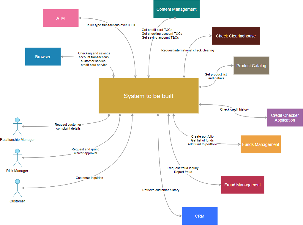
The system context diagram (also known as a level 0 DFD) is the highest level in a data flow diagram and contains only one process, representing the entire system, which establishes the context and boundaries of the system to be modeled. Thus, it is a high-level view of a system that defines the boundary between the system, or part of a system, and its environment, showing the external entities that interact with it.
A context diagram is typically included in a requirements document that is used early in a project to get agreement on the scope under investigation. It must be read by all project stakeholders and thus should be written in plain language, so that the stakeholders can understand items. System context diagrams. The objective of the system context diagram is to focus attention on external factors and events that should be considered in developing a complete set of systems requirements and constraints.
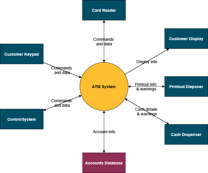
A context diagram gives an overview and it is the highest level in a data flow diagram, containing only one process (i.e. ATM) representing the entire system. It should be split into major processes that give greater detail and each major process may further split to give more detail. For example, ATM is decomposed into several smaller processes in a lower level DFD. In this way, the Content Diagram or Context-Level DFD is labeled a “Level-0 DFD” while the next level of decomposition is labeled a “Level-1 DFDs”, the next is labeled a “Level-2 DFDs”, and so on.
Edit this System Context Diagram
Identify System Scope with Context Diagram?
A context diagram is also known as the context data flow diagram or level 0 data flow diagram which helps you to identify scope, potential stakeholders, and build a better understanding of the context in which you are working. It shows the interactions between a system and other actors (external entities) with which the system is designed to interface. It typically used early in a project to get agreement on the scope and can be included in a requirements document.
A context diagram is designed to be an abstraction view, showing the system as a single process with its relationship to external entities. It represents the entire system as a single bubble with input and output data indicated by incoming/outgoing arrows.
The system – the top-most process can be broken down into smaller and simpler parts or a lower-level DFD. Each of these can be broken down further (e.g. level 1 DFD, Level-2 DFD and so on). Once you’ve reached the lowest level of decomposed pieces of a subsystem, developers can think about how to start coding those functions.
Advantages of DFD
- Give a functional overview and the boundaries of the system.
- Communicate the existing system knowledge to the stakeholders with a simple visual representation.
- Provide a functional breakdown of the system