A block flow diagram (BFD) is a drawing of chemical processes used to simplify and understand the basic structure of a system suggested by Peters & Timmerhaus, in 2003. A BFD is the simplest form of the flow diagrams used in the industry. Blocks in a BFD can represent anything from a single piece of equipment to an entire plant. For a complex process, block flow diagrams can be used to break up a complicated system into more reasonable principle stages/sectors.
This flow diagram is used to explain the general material flows throughout an entire plant. They will be generalized to certain plant sectors or stages. These documents would help orient workers to the products and important operation zones of a chemical facility. There are several conventions regarding the construction and format of BFDs that are commonly used in the engineering community. Some of the recommended conventions are:
- Operations/equipment are represented with blocks
- Material flows are represented with straight lines with arrows giving the direction of flow
- Lines are horizontal and/or vertical, with turns at 90-degree angles
- Flows go from left to right whenever possible
- If lines cross, the horizontal line is continuous and the vertical line is broken
- Light streams (gases) are typically closer to the top of the BFD than are heavy streams (liquids or solids)
- Critical information unique to the process (such as a chemical reaction) is supplied
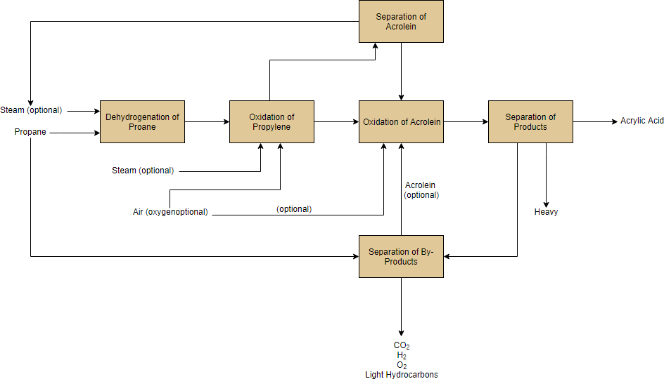
Block Flow Diagram Example – Oxidation of Propene to Acrylic Acid
Propane is dehydrogenated to propane, which is oxidized to acrolein first and then further oxidized to acrylic acid.
- The products are separated in the end to give acrylic acid and various by-products.
- The by-products are further separated to yield propane recycle stream.
- Each block in the BFD provided shows what each unit is doing along every step of the process. It also shows inlet and outlet streams, as well as byproducts and recycles streams.
A BFD in this style is helpful so that all materials can be seen, every step of the process is outlined, and by-products can be taken into consideration for waste removal/treatment.
Edit this Block Flow Diagram Example
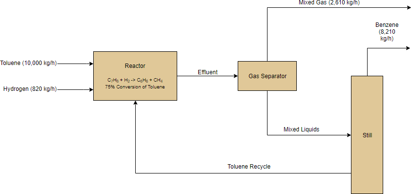
Block Flow Example – Production of Benzene
- Toluene and hydrogen are used as feedstocks for the production of benzene.
- The toluene and hydrogen are sent to a reactor, and the effluent is sent to a gas separator where the noncondensable gases are discharged from the system.
- The bottoms of the separator provide a liquid feed to a still where the lighter benzene gas is collected as the distillate and the bottom toluene draw is recycled back into the reactor.
The BFD provided shows the reaction, the stream names, and the mass flow of the inlets and outlets. There are many components of this system (heat exchangers and pumps, etc.) that are not represented because they are not vital for an understanding of the main features of the process.
Edit this Block Flow Diagram Example
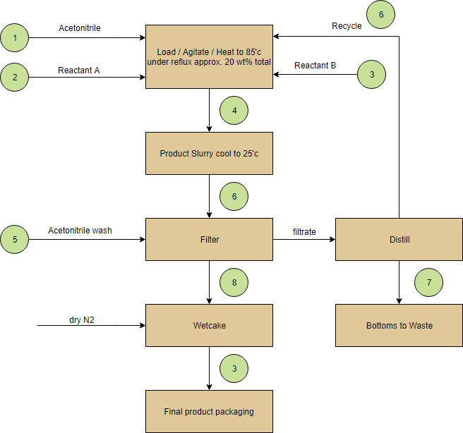
Block Flow for Hypothetical Chemical Process