The system context diagram (also known as a level 0 DFD) is the highest level in a data flow diagram and contains only one process, representing the entire system, which establishes the context and boundaries of the system to be modeled. It identifies the flows of information between the system and external entities (i.e. actors). A context diagram is typically included in a requirements document. It must be read by all project stakeholders and thus should be written in plain language, so the stakeholders can understand items
The Purpose of a System Context Diagram
The objective of the system context diagram is to focus attention on external factors and events that should be considered in developing a complete set of systems requirements and constraints. A system context diagram is often used early in a project to determine the scope under investigation. Thus, within the document.
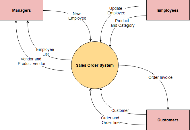
A system context diagram represents all external entities that may interact with a system. The entire software system is shown as a single process. Such a diagram pictures the system at the center, with no details of its interior structure, surrounded by all its External entities, interacting systems, and environments. Here is an example context diagram for a Sale Order System:
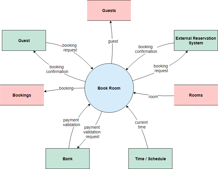
System Context Diagram Example – Hotel reservation system
This example shows the requirements of a computerized system that distributes and stores information of a hotel which enables hotel managers in managing their sales and online marketing, enabling them to upload their room rates and room available which can be easily seen by their sales channels. Sales channels may include online travel agencies, as well as conventional travel agencies.
System Context Diagram Example – ATM Machine
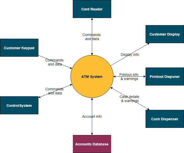
This diagram shows the Automatic Teller System software and the hardware that it interacts with. The arrows show the direction and type of data flowing between the software and each hardware element.