Component Diagram Tutorial
Component diagrams provide a simplified, high-order view of a large system. Classifying groups of classes into components supports the interchangeability and reuse of code. This diagram documents how these components are composed and how they interact in a system.
What is a Component Diagram in UML?
The main purpose of a component diagram is to show the structural relationships between the components of a system. In UML, Components are made up of software objects that have been classified to serve a similar purpose. Components are considered autonomous, encapsulated units within a system or subsystem that provide one or more interfaces. By classifying a group of classes as a component the entire system becomes more modular as components may be interchanged and reused. Component diagrams document the encapsulation of the component and the means by which the component interacts via interfaces.
Try it!
Finding an online Component Diagram tool? Just click the Draw button below to create your Component Diagram online. Visual Paradigm Online is free* and intuitive. You can also go through this Component Diagram tutorial to learn about Component Diagram before you get started.
Draw NowComponent Diagram Notations
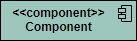
Component
A component is drawn as a rectangle with optional compartments stacked vertically. A component can be represented as just a rectangle with the component's name and the component stereotype text and/or icon. The component stereotype's text is "<<component>>" and the component stereotype icon is a rectangle with two smaller rectangles protruding on its left side.
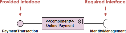
Component Interfaces
Provide Interface
Provided interfaces define "a set of public attributes and operations that must be provided by the classes that implement a given interface".
Required Interface
Required interfaces define "a set of public attributes and operations that are required by the classes that depend upon a given interface".
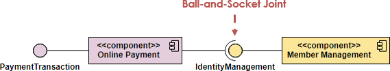
Component Assemblies
Components can be "wired" together using to form subsystems, with the use of a ball-and-socket joint.
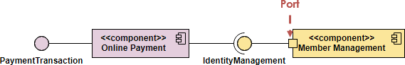
Port
A port (definition) indicates that the component itself does not provide the required interfaces (e.g., required or provided). Instead, the component delegates the interface(s) to an internal class.
When to Draw Component Diagram?
- Use component diagrams when you are dividing your system into components and want to show their interrelationships through interfaces.
- The breakdown of components into a lower-level structure.
How to Draw a Component Diagram?
- Decide on the purpose of the diagram
- Add components to the diagram, grouping them within other components if appropriate
- Add other elements to the diagram, such as classes, objects and interface
- Add the dependencies between the elements of the diagram
You can also:
- Draw subsystems for logical categorization of components

Component Diagram examples
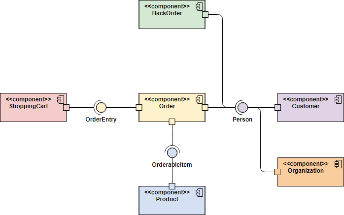
Order Processing System Component diagram example
One main benefit of Component diagrams if to simplify the high-level view of the system. The Figure below is a much larger view of what is involved in a online store. By using a component diagram we see the system as a group of nearly independent component or subsystems that interact with each other in a specifically defined way.
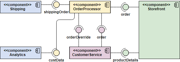
Each component is responsible for the action for which it is named and interface(s) it provides. As long as those requirements are maintained changes to one component will not percolate to other components.
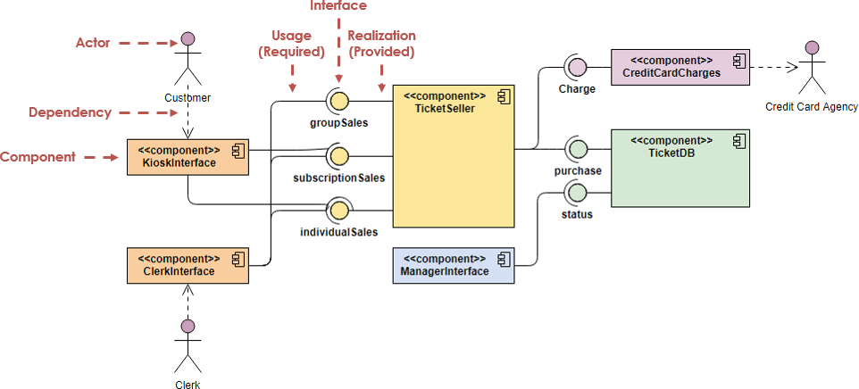
Ticket Selling System Component Diagram Example
There is a ticket seller component that sequentializes requests from both ticket selling system and clerks. A component that processes credit card charges; and the database containing the ticket information.
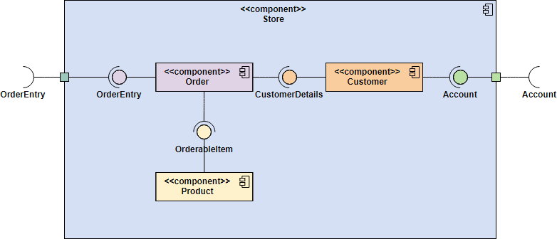
Component Example - Store Component - nested component structure
To show a nested component structure, you merely draw the component larger than normal and place the inner parts inside the name compartment of the encompassing component. The Figure below show's the Store's component nested structure.
Component Diagram Example - White-Box View of a Component
In the previous examples, those component diagrams are called black-box views. Ports are shown as squares bordering the component, these indicate how the interfaces of the component are used internally. Objects implementing a required interface are received via a port and objects implementing a provided interface are shared via a port.
In this example, the internal composition of components can also be modeled using component diagrams, this is called a white-box view of the diagram because we can see inside.
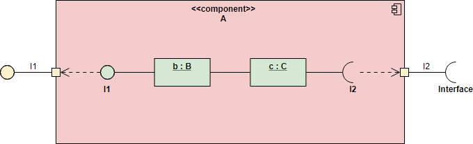
- Ports are shown as squares bordering the component, these indicate how the interfaces of the component are used internally.
- Objects implementing a required interface are received via a port and objects implementing a provided interface are shared via a port.
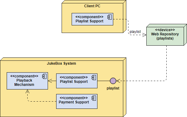
Component Diagram Example - Components in Deployment Diagram
Models the physical deployment of software components with UML deployment diagram. In deployment diagram, hardware components (e.g. web server, mail server, application server) are presented as nodes, with the software components that run inside the hardware components presented as artifacts.
Want to draw a Component Diagram?
You've learned what a Component Diagram is and how to draw a Component Diagram step-by-step. It's time to get your hands dirty by drawing a Component Diagram of your own. Draw UML diagrams free* with Visual Paradigm Online. It's easy-to-use, intuitive.
Draw Now* The Free edition supports free usage of Visual Paradigm Online for non-commercial use only.