Logic gates are the heart of digital electronics. Logic circuits are designed to perform a particular function, understanding the nature of that function requires a logic circuit truth table. When logic gates are connected they form a circuit. A gate is an electronic device that is used to compute a function on a two-valued signal. Logic gates are the basic building block of digital circuits.
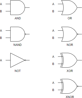
Gate Diagram symbols
The logic diagram consists of gates and symbols that can directly replace an expression in Boolean arithmetic. A logic gate is a device that can perform one or all of the Boolean logic operations AND, NAND, NOR, NOT, OR, XNOR, and XOR. All types of logic gate, except NOT, accept two binary digits as input, and produce one binary digit as output. NOT gates accept only one input digit.
Each one has a different shape to show its particular function. The inputs (Boolean variables) enter at the left of the symbol and the output leaves from the right. When combined, several gates can make a complex logical evaluation system that has many inputs and outputs. Digital computers are designed by connecting thousands, or millions, of these gates to together.
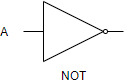
NOT gate
The NOT gate is a forward arrow with a small circle at the output. The circle part of the symbol is what says that the output is negating the input.
| A | Output |
| 0 | 1 |
| 1 | 0 |
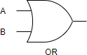
OR gate
The OR gate has a curved input side and a sharply pointed output.
| A | B | Output |
| 0 | 0 | 0 |
| 0 | 1 | 1 |
| 1 | 0 | 1 |
| 1 | 1 | 1 |
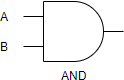
AND gate
The AND gate has a flat input side and round output side.
| A | B | Output |
| 0 | 0 | 0 |
| 0 | 1 | 0 |
| 1 | 0 | 0 |
| 1 | 1 | 1 |
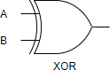
Exclusive OR (XOR) gate
The exclusive or gate symbol is just like the OR gate but it has an additional curved line crossing the inputs.
| A | B | Output |
| 0 | 0 | 0 |
| 0 | 1 | 1 |
| 1 | 0 | 1 |
| 1 | 1 | 0 |
Logic Gate Symbol Summary
Create Logic Diagram faster and better
Need to draw logic gate diagrams? Looking for a logic circuit tool? Visual Paradigm’s logic diagram tool features a handy diagram editor that allows you to draw logic diagrams swiftly. The logic gate software has all.
Edit this Logic Diagram example
Edit this Logic Diagram template
