Flowcharts allow you to draw a picture of the way a process works so that you can understand the existing process and develop ideas about how to improve it. Since humans are primarily a visual species, a picture of a process conveys information more efficiently than a written or verbal description. Making a process visible also renders it easier to manage and captures the subtle interactions among components.
Flowcharts can provide a step-by-step diagram for mapping out complex situations, such as programming or business workflow. There are many types of flow charts including swimlanes, such as cross-functional, opportunity or deployment flowchart.
Use Flowchart in Different Levels of Detail
A high-level flowchart, showing six to 12 steps, gives a panoramic view of a process. These flowcharts show clearly the major blocks of activity, or the major system components, in a process.
High-level flowcharts are especially useful in the early phases of a project. A detailed flowchart is a close-up view of the process, typically showing dozens of steps. These flowcharts make it easy to identify rework loops and complexity in a process.

Detailed flowcharts are useful after teams have pinpointed issues or when they are making changes in the process.
(*Source – ASQ – What is a Flowchart?)
When to Use a Flow Chart
- When document a process
- When planning a project
- When you need to define or analyze an existing process.
- When you need to standardize or redesign a process.
- When you need to find areas for improvement in a process such as unnecessary steps, gaps, barriers, etc.
The Benefits of Using a Flowchart
- Serve as a basis for designing new processes and help a team understand whether a process occurs in one or multiple ways
- Facilitates the team’s common understanding of the steps in a process and uses this knowledge to collect data, identify problems, focus discussions, and identify resources among team members.
- Identify steps and add values to the internal or external customer, including delays; needless storage and transportation; unnecessary work, duplication, and added expense; breakdowns in communication.
- Enables comparison of the way the process occurs with the planned or ideal flow
The Elements of a Flowchart
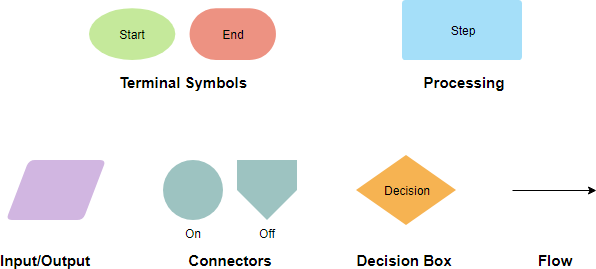
Flowcharts are diagrams that use shapes to show the types and flow of steps in a process. The shapes represent different types of steps or actions.
Terminal Symbol: Every flowchart has a unique starting point and an ending point. The flowchart begins at the start of the terminator and ends at the stop terminator.
- The Starting Point is indicated with the word START inside the terminator symbol.
- The Ending Point is indicated with the word STOP inside the terminator symbol.
- There can be only one START and one STOP terminator in your entire flowchart. In case a program logic involves a pause, it is also indicated with the terminal symbol.
Input /Output Symbol: This symbol is used to denote any input/output function in the program. Thus if there is any input to the program via an input device, like a keyboard, tape, card reader, etc. it will be indicated in the flowchart with the help of the Input / Output symbol.
Similarly, all output instructions, for output to devices like printers, plotters, magnetic tapes, disk, monitors, etc. are indicated in the Input / Output symbol.
Process Symbol: A process symbol is used to represent arithmetic and data movement instructions in the flowchart. All arithmetic processes of addition, subtraction, multiplication, and division are indicated in the process symbol. The logical process of data movement from one memory location to another is also represented in the process box. If there are more than one process instructions to be executed sequentially, they can be placed in the same process box, one below the other in the sequence in which they are to be executed.
Decision Symbol: The decision symbol is used in a flowchart to indicate the point where a decision is to be made and branching done upon the result of the decision to one or more alternative paths. The criteria for decision making is written in the decision box. All the possible paths should be accounted for. During execution, the appropriate path will be followed depending upon the result of the decision.
Flow: Flow links are solid lines with arrowheads that indicate the flow of operation. They show the exact sequence in which the instructions are to be executed. The normal flow of the flowchart is depicted from top to bottom and left to right.
Connectors: In situations, where the flowcharts become big, it may so happen that the flowlines start crossing each other at many places confusing. This will also result in making the flowchart difficult to understand.
Also, the flowchart may not fit in a single page for big programs. Thus whenever the flowchart becomes complex and spreads over several pages connectors are used. The connector represents entry from or exit to another part of the flowchart.
A connector symbol is indicated by a circle and a letter or a digit is placed in the circle. This letter or digit indicates a link.
A pair of such identically labeled connectors are used to indicate a continued flow in situations where flowcharts are complex or spread over more than one page. Thus a connector indicates an exit from some section in the flowchart and entry into another section of the flowchart.
Six Steps for Creating Flowchart
Many teams find it easy to the flowchart on large poster-size sheets, using sticky notes for process steps, or on whiteboards. Alternatively, use a flowcharting tool with a projector to the working flowchart on the wall to facilitate the discussion, this allows the team to brainstorm, move or add steps around much easier.
When developing a flowchart, include people with knowledge of the problem being discussed.
- Identify the goal for creating the flowchart and the level of detail required-high or detailed.
- Assemble the people who know the process best and outline the process steps.
- Define the first and last steps in the process.
- Begin documenting the process steps in sequence. Some steps may be parallel-they happen at the same time. Describe the process as it exists, not the ideal. Most flow charts are made up of three main types of symbol:
- Circles, which signify the start or end of a process.
- Rectangles or squares which show instructions or actions.
- Diamonds which show decisions that must be made
- Work through the entire process, showing actions and decisions appropriately in the order they occur. Link these together using arrows to show the flow of the process. (Tip: Self-adhesive notes are a flexible way to document steps, using one note for each step. This allows you to easily change the order or add new steps.)
- Validate your flow chart. Work from step to step asking yourself and others if you have correctly represented the sequence of actions and decisions involved in the process.
- Identify areas for improvement and redesign the process.
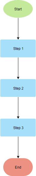
Flowchart Template with Linear Flow
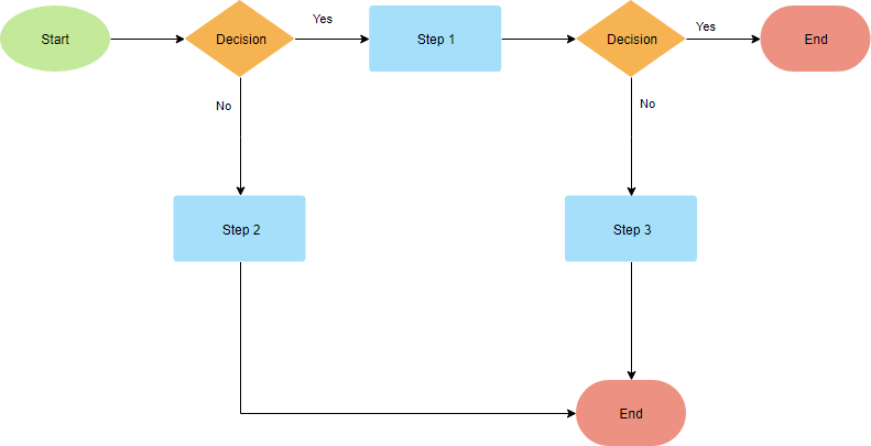
Flowchart Template with Multiple Paths
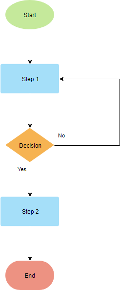
Flowchart Template with Recursive Path
Swimlane Flowchart
A basic flowchart consists of a series of process steps connected by arrows showing the order of operations which is regarded as one dimensional. A swimlane flowchart (also known as a cross-functional flowchart) provides an additional dimension by assigning each process step to a category. Most often the category is a stakeholder (person, role, or department that visually distinguishes job sharing and responsibilities for sub-processes of a business process. The swimlanes may be arranged either horizontally or vertically.
What are the Differences? Flowchart vs Swimlane Flowchart
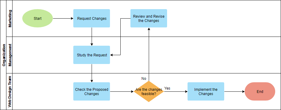
The swimlane flowchart differs from other flowcharts in that processes and decisions are grouped visually by placing them in lanes. Parallel lines divide the chart into lanes, with one lane for each person, group or subprocess. Lanes are labeled to show how the chart is organized.
In the example below, the vertical direction represents the sequence of events in the overall process, while the horizontal divisions depict what sub-process is performing that step. Arrows between the lanes represent how information or material is passed between the sub-processes.
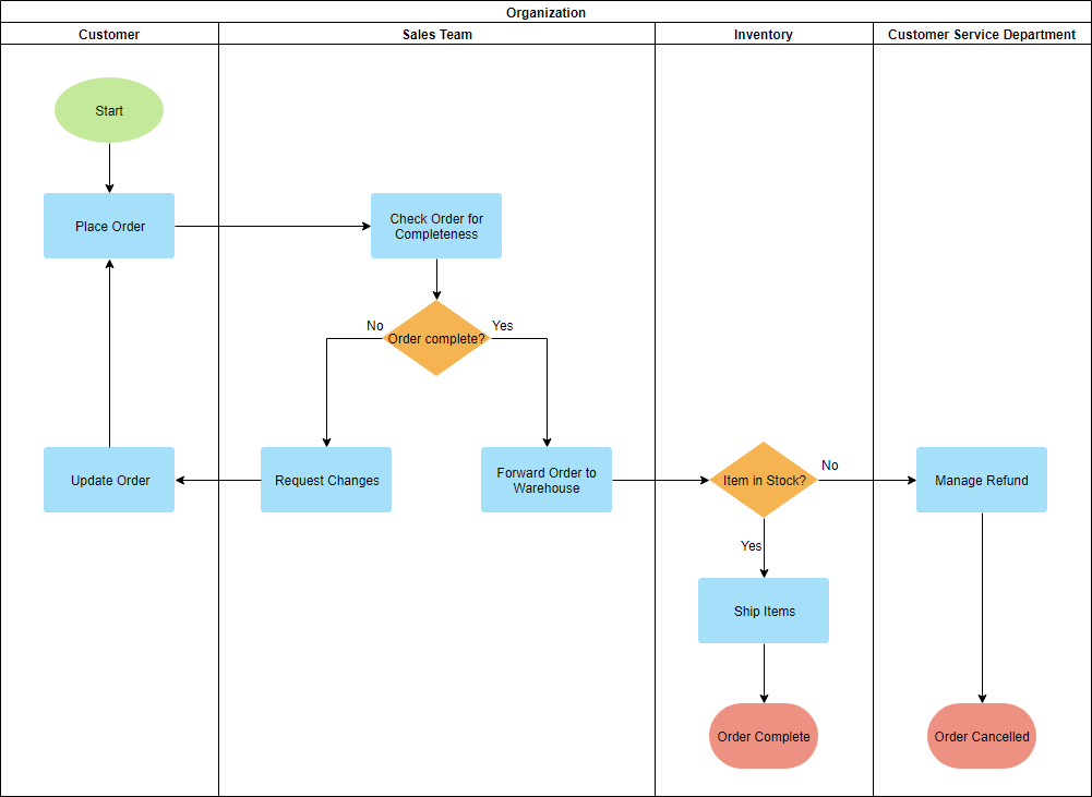
Alternately, the flow can be rotated so that the sequence reads horizontally from left to right, with the roles involved being shown at the left edge. This can be easier to read and design since computer screens are typically wider than they are tall, which gives an improved view of the flow.
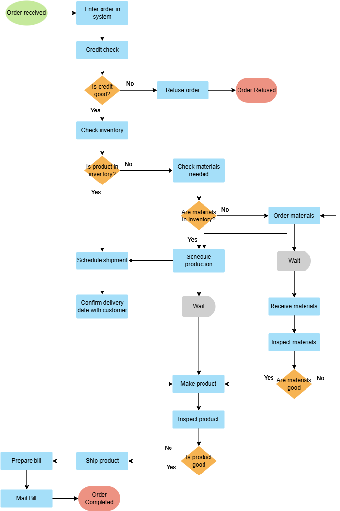
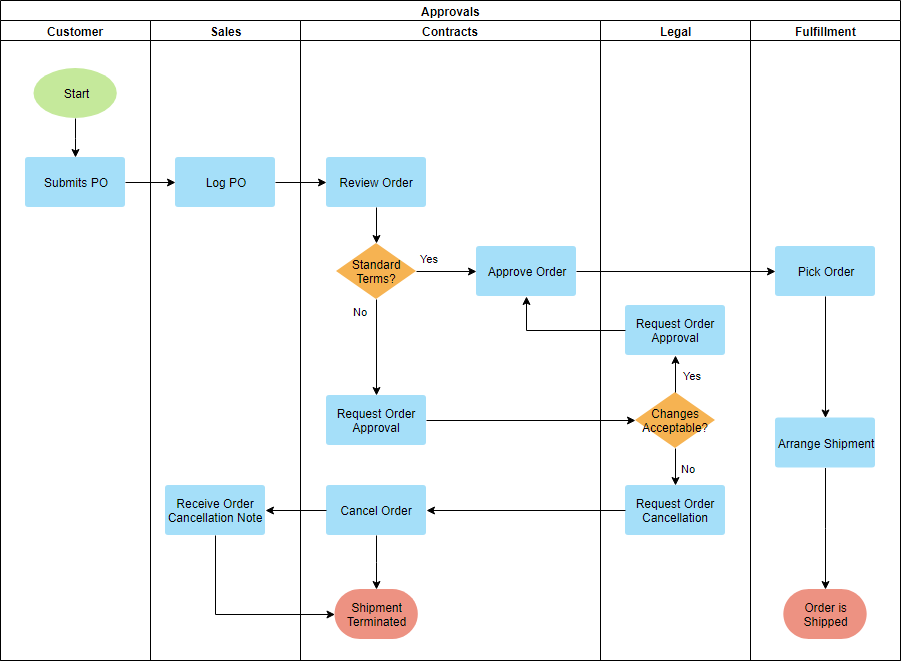
Deployment Swimlane Flowchart
The shapes used in drawing a deployment flowchart are the same as those in a standard flowchart with swimlane notations. A deployment flowchart combines two key features:
- The sequence of steps in a process
- Who is responsible for which deployment step
It shows the steps in a process and also shows which person or group is involved in the step response. The example below shows the responsible groups listed across the top. These groups are Production, Administration, and Marketing. You could draw a deployment flowchart that lists people instead of groups. The benefit of a deployment flowchart is that it shows where work is handed from one person or group to another which are the places where misunderstandings and errors could be minimized.
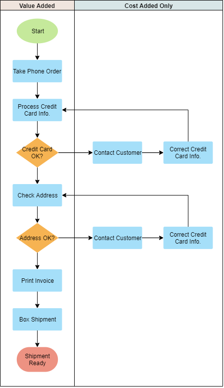
Opportunity Swimlane Flowchart
Opportunity flowcharts (also known as Value-Added flowcharts) are used to identify which steps in a process are value-added or wasteful. It separates those essential steps for making a product or service from those cost-added activities.
- Create an opportunity swimlane flowchart is to identify all the process steps.
- Determine which of the steps add value from the perspective of the customers and which do not.
- Create the flowchart for each step in the appropriate column.
Value Added vs Non Value Added Activities
Any time you begin analyzing a process, you want to look at each step and determine if it is contributing to the value of the desired output. Each step can be classified into one of three categories:
- Value-added activities are those processes that must be completed to satisfy your customer base.
- Non-value added, but necessary activities are production or service-related activities that simply add cost to, or increase time spent on, a product service without increasing its market value (i.e. 8 classic wastes). For example, the repair of machines, storage of inventory, moving materials, maintenance, and inspections
- Non-value added (waste) activities consume resources but create no value for the customer. Even if they stopped and they would be invisible to the end-user or customer.
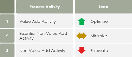
In conclusion, value-added activities should be further optimized for seeking continuous improvement and growth of an organization, while the non-value added activities should be eliminated, or at least minimized as much as possible.