The classic Structured Systems Analysis and Design Methodology (SSADM) by Chris Gane and Trish Sarson. SSADM is better known as Data Flow Diagrams. This method was developed for the government of Great Britain at the beginning of the 80th of the past century. It was accepted as the national standard of Great Britain for information systems development in 1993.
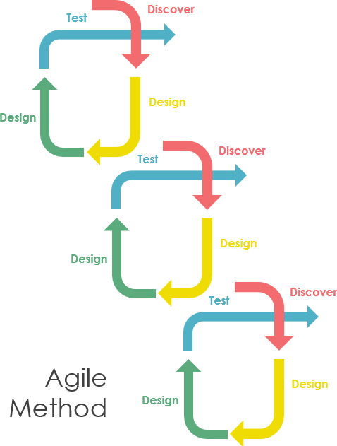
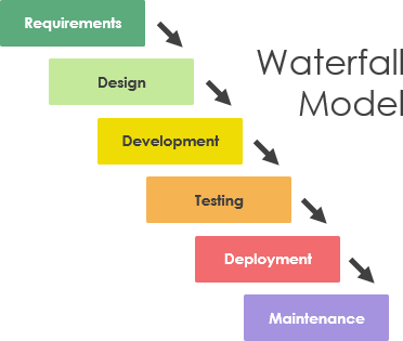
SSADM is a waterfall method for the analysis and design of information systems. SSADM can be thought to represent the rigorous document-led approach to system design and contrasts with more contemporary agile methods such as DSDM or Scrum.
Agile method:
Waterfall model:
What is SSADM?
The three most important techniques that are used in SSADM are as follows:
Data Flow Modeling
The process of identifying, modeling and documenting how data moves around an information system. Data Flow Modeling examines processes (activities that transform data from one form to another), data stores (the holding areas for data), external entities (what sends data into a system or receives data from a system), and data flows (routes by which data can flow).
Logical Data Modeling
The process of identifying, modeling and documenting the data requirements of the system being designed. The result is a data model containing entities (things about which a business needs to record information), attributes (facts about the entities) and relationships (associations between the entities).
Entity Event Modeling
A two-stranded process: Entity Behavior Modelling, identifying, modeling and documenting the events that affect each entity and the sequence (or life history) in which these events occur, and Event Modelling, designing for each event the process to coordinate entity life histories.
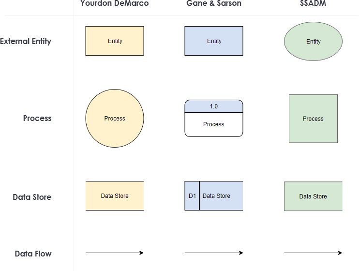
Different DFD Notations (Yourdon / DeMarco vs Gane & Sarson vs SSADM)
Out of the three modeling techniques above, Data Flow modeling is the core of the SSADM. SSADM is mainly based on the data flow diagrams, which is a simple and highly effective systems analysis and design (decomposition) methodology.
- It simply uses just four symbols, and it is excellent for communicating with non-technical users.
- A proposed or existing system can be analyzed and decomposed to the level required (the deeper levels being more technical), which assists in exposing efficiency, modularity and duplication issues.
SSADM Symbols
There are several notations for displaying data-flow diagrams, including Edward Yourdon, Larry Constantine, Tom DeMarco, Chris Gane, and Trish Sarson. Here listed below the three most widely used DFD notations:
- Yourdon and/or De Marco,
- Gane & Sarson, and
- SSADM(Structured System Analysis and Design Methodology)
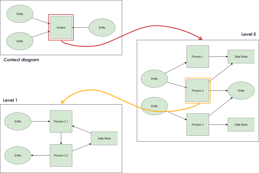
Top-Down Decomposition Techniques in SSADM
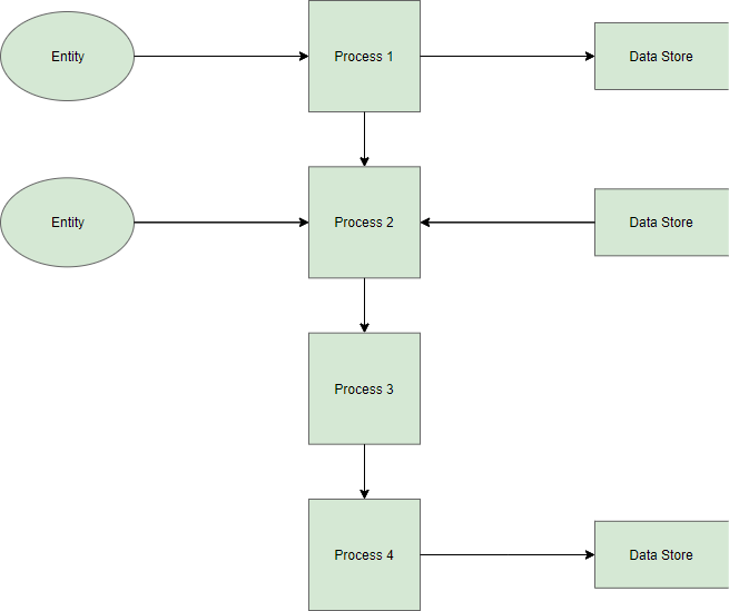
Top-down decomposition, also called leveling, is a technique used to show more detail in lower-level DFDs. Leveling is done by drawing a series of increasingly detailed diagrams until the desired degree of detail is reached. As shown in the Figure, DFD Leveling is first displaying the targeted system as a single process, and then showing more detail until all processes are functional primitives.
DFD(data flow diagram) can be drawn to represent the system of different levels of abstraction. Higher-level DFDs are partitioned into low levels-hacking more information and functional elements. Levels in DFD are numbered 0, 1, 2 or beyond. Here, we will see mainly 3 levels in the data flow diagram, which are: 0-level DFD, 1-level DFD, and 2-level DFD.
Numbering Convention
- Use a unique reference number for each processed symbol.
- Other process numbers are in the hierarchy of:
- (1, 2, 3,…);
- (1.1, 1.2, 1.3, …, 2.1, 2.2, 2.3,…);
- (1.1.1, 1.1.2, 1.1.3,…).
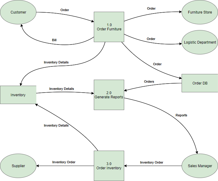
SSADM DFD Templates and Examples