Class Diagram Tutorial
What is a Class Diagram in UML?
A class diagram describes the structure of an object-oriented system by showing the classes in that system and the relationships between the classes. A class diagram also shows constraints, and attributes of classes.
Try it!
Finding an online Class Diagram tool? Just click the Draw button below to create your Class Diagram online. Visual Paradigm Online is free* and intuitive. You can also go through this Class Diagram tutorial to learn about Class Diagram before you get started
Draw NowClass Diagram Notations
Class
The UML representation of a class is a rectangle containing three compartments stacked vertically, as shown in the Figure:
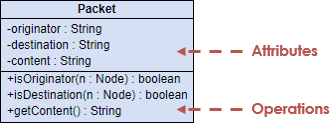
Attribute
The attribute section of a class lists each of the class's attributes on a separate line. The attribute section is optional, but when used it contains each attribute of the class displayed in a list format. The line uses this format: name : attribute type (e.g. cardNumber : Integer).
Operation
The operations are documented in the bottom compartment of the class diagram's rectangle, which also is optional. Like the attributes, the operations of a class are displayed in a list format, with each operation on its own line. Operations are documented using this notation: name (parameter list) : type of value returned (e.g. calculateTax (Country, State) : Currency).
Relationships
Association
Some objects are made up of other objects. Association specifies a "has-a" or "whole/part" relationship between two classes. In an association relationship, an object of the whole class has objects of part class as instance data.
In a class diagram, an association relationship is rendered as a directed solid line.
Unidirectional association - In a unidirectional association, two classes are related, but only one class knows that the relationship exists.
A unidirectional association is drawn as a solid line with an open arrowhead pointing to the known class.
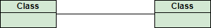
Bidirectional (standard) association - An association is a linkage between two classes. Associations are always assumed to be bi-directional; this means that both classes are aware of each other and their relationship, unless you qualify the association as some other type.
A bi-directional association is indicated by a solid line between the two classes.
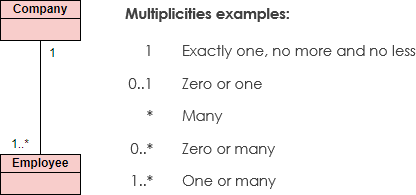
Multiplicity
Place multiplicity notations near the ends of an association. These symbols indicate the number of instances of one class linked to one instance of the other class. For example, one company will have one or more employees, but each employee works for one company only.
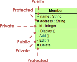
Visibility
Visibility is used to signify who can access the information contained within a class denoted with +, -, # and ~ as show in the figure:
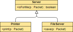
Generalization
A generalization is a relationship between a general thing (called the superclass) and a more specific kind of that thing (called the subclass). Generalization is sometimes called an "is a kind of" relationship and is established through the process of inheritance.
In a class diagram, generalization relationship is rendered as a solid directed line with a large open arrowhead pointing to the parent class.
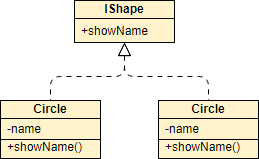
Abstract Classes and methods
In an inheritance hierarchy, subclasses implement specific details, whereas the parent class defines the framework its subclasses. The parent class also serves a template for common methods that will be implemented by its subclasses.
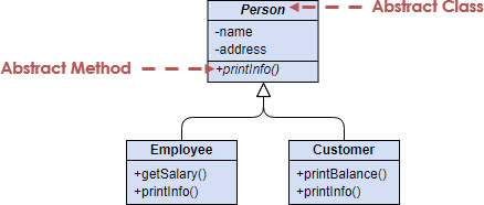
The name of an abstract Class is typically shown in italics; alternatively, an abstract Class may be shown using the textual annotation, also called stereotype {abstract} after or below its name.
An abstract method is a method that do not have implementation. In order to create an abstract method, create a operation and make it italic.
Realization
A realization is a relationship between two things where one thing (an interface) specifies a contract that another thing (a class) guarantees to carry out by implementing the operations specified in that contract.
In a class diagram, realization relationship is rendered as a dashed directed line with an open arrowhead pointing to the interface.
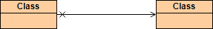
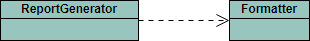
Dependency
Dependency indicates a "uses" relationship between two classes. In a class diagram, a dependency relationship is rendered as a dashed directed line.
If a class A "uses" class B, then one or more of the following statements generally hold true:
- Class B is used as the type of a local variable in one or more methods of class A.
- Class B is used as the type of parameter for one or more methods of class A.
- Class B is used as the return type for one or more methods of class A.
- One or more methods of class A invoke one or more methods of class B.
When to Draw Class Diagram?
Most of the UML diagrams can not be mapped directly with any object-oriented programming languages except class diagrams. In other words, class diagram ideally can have one to one mapping to UML class diagrams. Besides, class diagrams are useful in the following situations:
- Describing the static view of the system.
- Modeling the collaboration among the elements of the static view.
- Describing the functionalities performed by the system.
- Construction of software applications using object oriented languages.
- Performing code forward engineering for the target systems
- Classifying classes or components as library for future reuses
How to Draw a Class Diagram?
- Identify the objects in the problem domain, and create classes for each of them. (e.g. Teacher, Student, Course for an enrollment system)
- Add attributes for those classes (e.g. name, address, telephone for the Student class)
- Add operations for those classes (e.g. addStudent(student) for the Course class)
- Connect the classes with appropriate relationships (e.g. Relate Teacher and Course with an association)
- Optionally specify the multiplicities for association connectors' ends (e.g. Input 0..3 for the Course side of the association that connects Teacher and Course, to signify that one teacher can teach multiple up to three courses)
You can also:
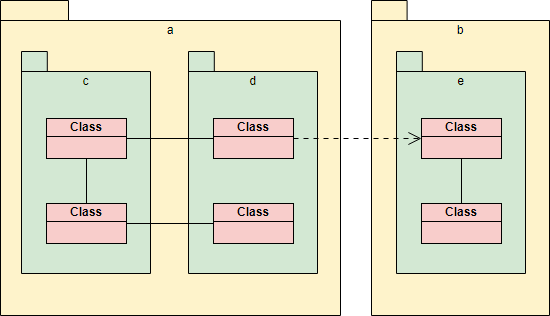
- Draw packages for logical categorization of classes
Class Diagram Examples
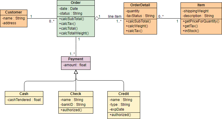
The class diagram example below shows the classes involved in a sales order system. Notice the use of <<enumeration>> class in the class model.

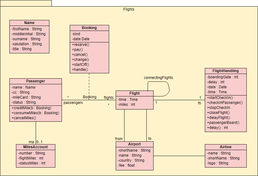
The class diagram example below shows a set of classes related to flight management. The classes are grouped under a package.
Want to draw a Class Diagram?
You've learned what a Class Diagram is and how to draw a Class Diagram step-by-step. It's time to get your hands dirty by drawing a Class Diagram of your own. Draw UML diagrams free* with Visual Paradigm Online. It's easy-to-use, intuitive.
Draw Now* The Free edition supports free usage of Visual Paradigm Online for non-commercial use only.