The Piping and Instrumentation Diagram (P&ID) is a graphical representation of the actual process plant using various symbols that represent actual equipment. It is a detailed diagram in the process industry that shows all piping including physical sequences of branches, reducers, valves, equipment, instrumentation and control interlocks.
P&IDs are originally drawn up at the design stage from a combination of process flow sheet data, the mechanical process equipment design, and the instrumentation engineering design. During the design stage, the diagram also provides the basis for the development of system control schemes, allowing for further safety and operational investigations, such as a Hazard and operability study (HAZOP).
The Elements of P&ID Diagram
A piping and instrumentation diagram (P&ID) shows the interconnection of process equipment and the instrumentation used to control the process. A standard set of symbols is used. The figure below shows some of the symbols available in Visual Paradigm Online Diagrams – the best piping and instrumentation diagram tool.
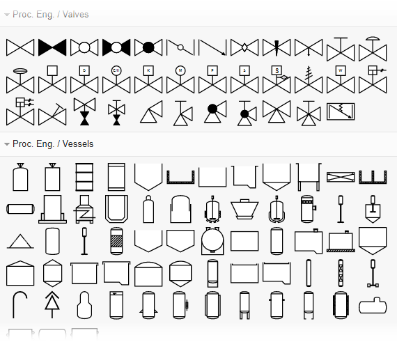
P&ID Diagram usually contains the following information:
Mechanical equipment Elements
- Pressure vessels, columns, tanks, pumps, compressors, heat exchangers, furnaces, wellheads, fans, cooling towers, turbo-expanders, pig traps (see ‘symbols’ below)
- Bursting discs, restriction orifices, strainers and filters, steam traps, moisture traps, sight-glasses, silencers, flares and vents, flame arrestors, vortex breakers, eductors
Process piping, sizes and identification Elements
- Pipe classes and piping line numbers
- Flow directions
- Interconnections references
- Permanent start-up, flush and bypass lines
- Pipelines and flowlines
- Blinds and spectacle blinds
- Insulation and heat tracing
Process control instrumentation and designation Elements
- Valves and their types and identifications (e.g. isolation, shutoff, relief and safety valves, valve interlocks)
- Control inputs and outputs (sensors and final elements, interlocks)
- Miscellaneous – vents, drains, flanges, special fittings, sampling lines, reducers, and swages
- Interfaces for class changes
- Computer control system
- Identification of components and subsystems delivered by others
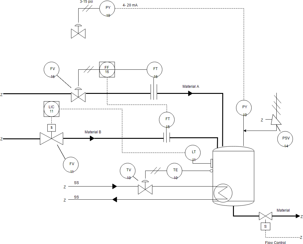
P&ID Example – Mixing Station
This is a P&ID diagram example for the mixing station. It contains shapes like valve, tank and various connectors. Use this P&ID diagram template as a starting point in creating your P&ID. The figure below illustrates a very small and simplified P&ID: