Uses cases are widely accepted as the best approach to capturing system requirements, in particular, functional requirements. Robustness analysis helps you to bridge the gap from Use Cases and Domain Classes, and the model-view-control (MVC) software architecture. In a nutshell, it’s a way of analyzing your use case model and identifying the first-guess set of objects for each use case. These are classified into boundary objects, entity objects, and controllers.
Robustness Diagram Stereotypes
Robustness analysis, which is an informal diagram in UML, was part of Jacobson’s Objectory method. It is similar to a UML collaboration diagram, in that it shows the objects that participate in the scenario and how those objects interact with each other. Robustness analysis is not exactly a core part of UML; instead, it requires the use of some stereotypes.
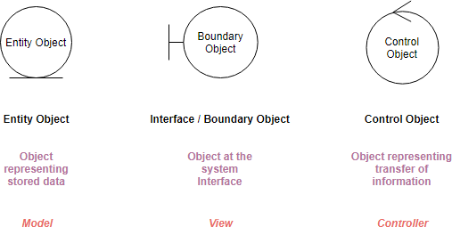
Boundary Object – Represents the interfaces between the actors and the system.
Depending upon the type of the actor, a boundary class is required to provide a user interface, external system (legacy system) interface or device interface.
Control objects – Represents the use case logic and coordinates the other classes.
It separates the interface classes from business logic classes. In ASP.NET, the code-behind classes can be regarded as Control classes.
Entity Object – Manages the information the system needs to provide the required functionality.
Usually, entity classes are business-specific. They are information experts and encapsulate business knowledge. Most of the time, entity classes are persistent classes that can be used to generate database schema directly.
Robustness Diagram – 4 Connection Rules
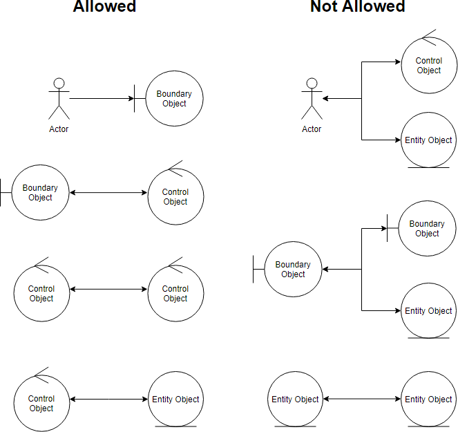
Keep in mind that both boundary objects and entity objects are nouns and that controllers are verbs. Nouns can’t talk to other nouns, but verbs can talk to either nouns or verbs. Here I listed the four basic connection rules which should always be mind:
- Actors can only talk to boundary objects.
- Boundary objects can only talk to controllers and actors.
- Entity objects can only talk to controllers.
- Controllers can talk to boundary objects, entity objects, and other controllers, but not to actors.
Why Model-View-Controller Architecture?
Model–View–Controller (usually known as MVC) is a software architecture that separates an application into three main logical components: the model, the view, and the controller. Each of these components is built to handle specific development aspects of an application.
MVC is one of the most frequently used industry-standard software development frameworks to create scalable and extensible projects. It works well with object-oriented programming since the different models, views, and controllers can be treated as objects and reused within an application. The three parts of MVC are interconnected. The view displays information and accepts user input. The controller accepts user input and updates the model and view accordingly.
Below is a description of each aspect of MVC:
Model – Represents the data of the application. This may be a database, file, or a simple object
View – The user interface of the application. Examples include displaying a window or buttons or text within a window. It includes anything that the user can see.
Controller – Used to handle any form of input such as clicks or browser events. It’s the controller’s job to update the model when necessary (i.e. if a user changes their name).
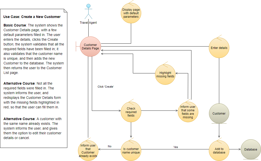
Robustness Analysis Diagram Example – Create a New Customer
The initial use case description is put beside the diagram in the left as a label. We can use it as a basis for creating the Robustness Analysis Diagram; making it traceable with the original description.
The robustness diagram is often be used for modeling use case scenarios as well, typically represented by several sequence diagrams.