Data modeling is a technique to document a software system using entity relationship diagrams (ER Diagram) which is a representation of the data structures in a table for a company’s database. It is a very powerful expression of the company’s business requirements. Data models are used for many purposes, from high-level conceptual models, logical to physical data models and typically represented by the entity-relationship diagram. It serves as a guide used by database analysts and software developers in the design and implementation of a system and the underlining database.
What is Entity Relationship Diagram?
An Entity Relationship Diagram (ERD) is a pictorial representation of the information that can be captured by a database. Such a “picture” serves two purposes. It allows database professionals to describe an overall design concisely yet accurately. An ER Diagram can be easily transformed into the relational schema. There are three components in ERD: Entities, Attributes, and Relationships.
Entities
The number of tables you need for your database – Entities is the basic objects of ERDs. These are the tables of your database, i.e. students, courses, books, campus, employees, payment, projects. A specific example of an entity is called an instance. Each instance becomes a record or a row in a table.
Attributes
Information such as property, facts you need to describe each table – Attributes are facts or descriptions of entities. They are also often nouns and become the columns of the table. For example, for entity students, the attributes can be first name, last name, email, address, and phone numbers.
- Primary Key is an attribute or a set of attributes that uniquely identifies an instance of the entity. For example, for a student entity, student number is the primary key since no two students have the same student number. We can have only one primary key in a table. It identifies uniquely every row and it cannot be null.
- Foreign key is a key used to link two tables together. Typically you take the primary key field from one table and insert it into the other table where it becomes a foreign key (it remains a primary key in the original table). We can have more than one foreign key in a table.
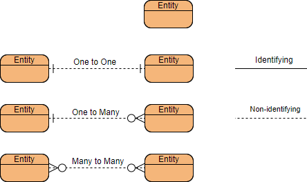
Relationships: How tables are linked together – Relationships are the associations between the entities. Verbs often describe relationships between entities. We will use Crow’s Foot Symbols to represent the relationships. Three types of relationships are discussed in this lab. If you read or hear cardinality ratios, it also refers to types of relationships.
Cardinality: it defines the possible number of occurrences in one entity which is associated with the number of occurrences in another. For example, ONE team has MANY players. When present in an ERD, the entity Team and Player are inter-connected with a one-to-many relationship.
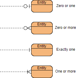
In an ER diagram, cardinality is represented as a crow’s foot at the connector’s ends. The three common cardinal relationships are one-to-one, one-to-many, and many-to-many. Here is some examples cardinality of relationship in ERD:
ERD Example – Customer Appointment
Suppose we have the following business scenario:
- One Customer may be making one or more Appointments
- One Appointment Must be made by One and Only One Customer
- The cardinality linked from Customer to Appointments is 0 to many
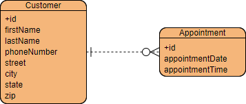
The ERD above using the Crow’s Foot notation:
- Entities are shown in a box with attributes listed below the entity name.
- Relationships are shown as solid lines between two entities.
- The minimum and maximum cardinalities of the relationship linked between Customer and Appointment are shown with either a straight line and hash marks, or a crow’s foot as shown in the figure below.
Conceptual, Logical and Physical data models
A general understanding to the three data models is that business analyst uses a conceptual and logical model to model the business objects exist in the system, while database designer or database engineer elaborates the conceptual and logical ER model to produce the physical model that presents the physical database structure ready for database creation. The table below shows the difference between the three data models. An ER model is typically drawn at up to three levels of abstraction:
- Conceptual ERD / Conceptual data model
- Logical ERD / Logical data model
- Physical ERD / Physical data model
While all the three levels of an ER model contain entities with attributes and relationships, they differ in the purposes they are created for and the audiences they are meant to target.
Conceptual model vs Logical model vs Data model:
| ERD feature | Conceptual | Logical | Physical |
|---|---|---|---|
| Entity (name) | Yes | Yes | Yes |
| Relationship | Yes | Yes | Yes |
| Column | Yes | Yes | |
| Column’s Type | Optional | Yes | |
| Primary Key | Yes | ||
| Foreign Key | Yes |
In the table, it summarizes the characteristics of the three data model:
- The conceptual model is to establish the entities, their attributes, and their relationships.
- The logical data model defines the structure of the data elements and set the relationships between them.
- The physical Data Model describes the database-specific implementation of the data model.
Conceptual data model
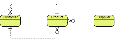
Conceptual ERD models the business objects that should exist in a system and the relationships between them. A conceptual model is developed to present an overall picture of the system by recognizing the business objects involved. It defines what entities exist, NOT which tables. For example, ‘many to many’ tables may exist in a logical or physical data model but they are just shown as a relationship with no cardinality under the conceptual data model.
Conceptual data model example
NOTE: Conceptual ERD supports the use of generalization in modeling the ‘a kind of’ relationship between two entities, for instance, Triangle, is a kind of Shape. The usage is like generalization in UML. Notice that only conceptual ERD supports generalization.
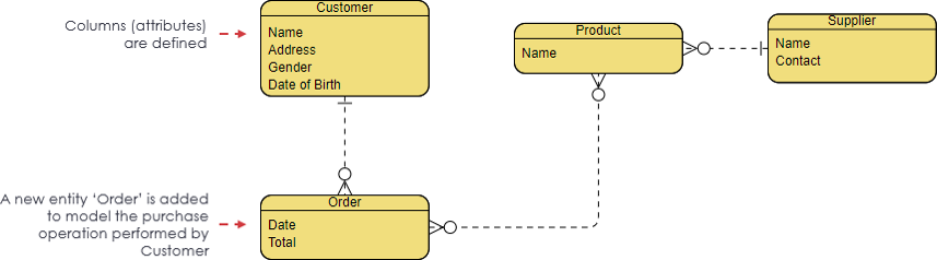
Logical data model
Logical ERD is a detailed version of a Conceptual ERD. A logical ER model is developed to enrich a conceptual model by defining explicitly the columns in each entity and introducing operational and transactional entities. Although a logical data model is still independent of the actual database system in which the database will be created, you can still consider that if it affects the design.
Logical data model example
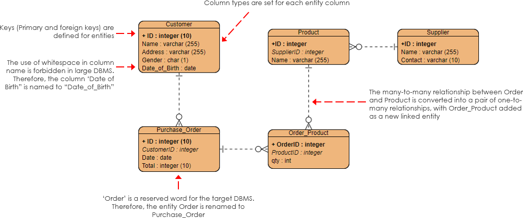
Physical data model
Physical ERD represents the actual design blueprint of a relational database. A physical data model elaborates on the logical data model by assigning each column with type, length, nullable, etc. Since a physical ERD represents how data should be structured and related in a specific DBMS it is important to consider the convention and restriction of the actual database system in which the database will be created. Make sure the column types are supported by the DBMS and reserved words are not used in naming entities and columns.
Physical data model example
Edit this physical ERD example
Conclusion
The main goal of a designing data model is to make certain that data objects offered by the functional team are represented accurately. We should first start from the conceptual data model and as more and more information available we add more details to refine it from conceptual to the logical model. Finally, when we know exactly how to implement the database of our system, we can refine our logical model into the physical data model which can directly map between the diagram and the actual database system.