Arrow Diagram (also known as, activity network diagram, or arrow programming method) is used to determine the optimal sequence of events and their interconnectivity. It is often considered as a variation of PERT (program evaluation and review technique) chart. An arrow diagram is an effective way to represent the required order of tasks in a project or process, the best schedule for the entire project, and potential scheduling and resource problems and their solutions.
An arrow diagram is often used for scheduling and to determine the critical path through nodes that represents a work plan for identifying critical operations visually; it also lets you calculate the “critical path” of the project that can affect the timing of the entire project and where the addition of resources can speed up the project.
Arrow Diagram Simple Example
Arrow Diagram is used for scheduling activities in a project plan. Precedence relationships between activities are represented by circles connected by one or more arrows. The length of the arrow may be used to represent the duration of the relevant activity, or with a figure. Arrow Diagram only shows finish-to-start relationships, meaning that each activity is completed before the successor activity starts.

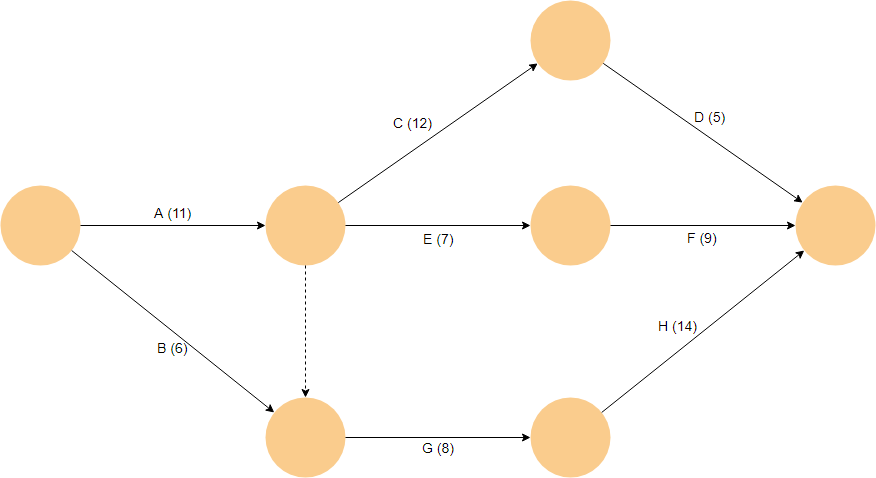
In the example above, what is the duration of the project? Before we find the duration of the project, let’s first find the number of paths:
Several paths exist from start to end.
- Duration of path A, C, D = 11 + 12 + 5 = 28
- Duration of path A, E, F = 11 + 7 + 9 = 27
- Duration of path B, G, H = 6 + 8 + 14 = 28
- Duration of path A, G, H = 11 + 8 + 14 = 33
To complete the project, longest path needs to be completed. Thus, the duration of the project is equal to 35.
Arrow Diagram Examples and Templates
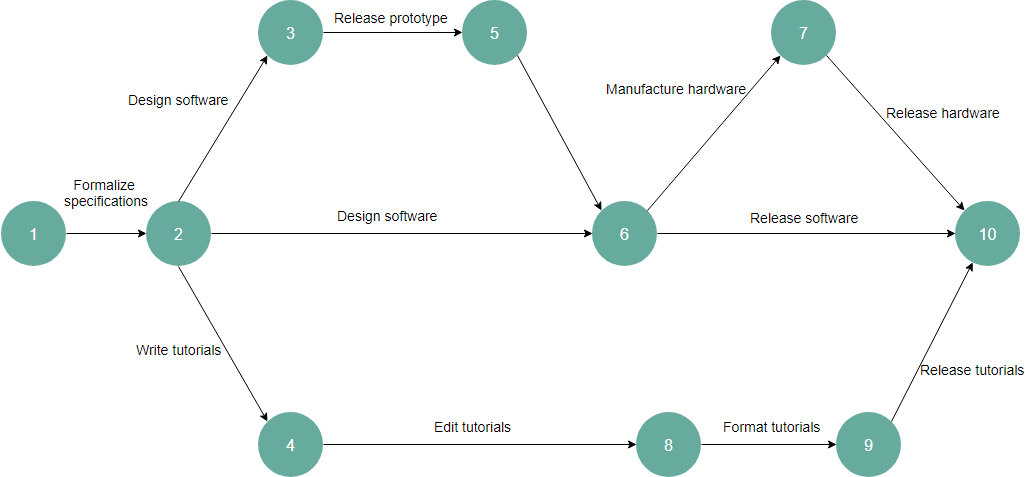
Software Development Example

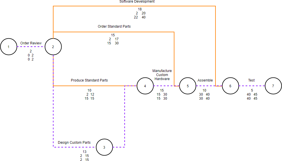
Air Control Example

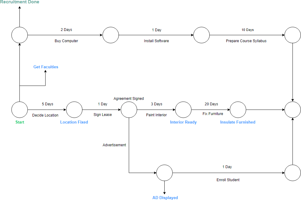
Project Management Example
