Functional Flow Block Diagram Guide
A functional flow block diagram (FFBD) is a multi-tier, time-sequenced, step-by-step flow diagram of a system’s functional flow. The FFBD notation was developed in the 1950s, and is widely used in classical systems engineering.
The Elements of Functional Flow Block Diagram

Function block: Each function on an FFBD should be separate and be represented by single box (solid line). Each function needs to stand for definite, finite, discrete action to be accomplished by system elements.
Function numbering: Each level should have a consistent number scheme and provide information concerning function origin. These numbers establish identification and relationships that will carry through all Functional Analysis and Allocation activities and facilitate traceability from lower to top levels.
Functional reference: Each diagram should contain a reference to other functional diagrams by using a functional reference (box in brackets).
Flow connector: Lines connecting functions should only indicate function flow and not a lapse in time or intermediate activity.
Flow direction: Diagrams should be laid out so that the flow direction is generally from left to right. Arrows are often used to indicate functional flows.
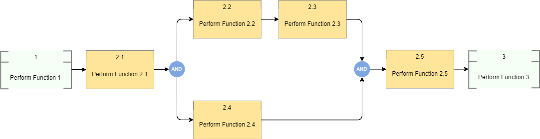
Summing gates: A circle is used to denote a summing gate and is used when AND/OR is present. AND is used to indicate parallel functions and all conditions must be satisfied to proceed. OR is used to indicate that alternative paths can be satisfied to proceed.
GO and NO-GO paths: “G” and “bar G” are used to denote “go” and “no-go” conditions. These symbols are placed adjacent to lines leaving a particular function to indicate alternative paths.
Contextual and administrative data: Each FFBD shall contain the following contextual and administrative data:
• Date the diagram was created
• Name of the engineer, organization, or working group that created the diagram
• Unique decimal delimited number of the function being diagrammed
• Unique function name of the function being diagrammed.
Top-down Decomposition
• FFBDs can be developed in a series of levels. FFBDs show the same tasks identified through functional decomposition and display them in their logical, sequential relationship.
• For example, the entire flight mission of a spacecraft can be defined in a top level FFBD, as shown in the Figure below.
• Each block in the first level diagram can then be expanded to a series of functions, as shown in the second level diagram for "perform mission operations."
• Each block in the second level diagram can be progressively developed into a series of functions, as shown in the third level diagram

Functional Flow Block Diagram Notation illustrated

Edit this FFBD illustration online
Functional Flow Block Diagram Example