A process flow diagram (PFD) is a diagram commonly used in chemical and process engineering to indicate the general flow of plant processes and equipment. The PFD contains the bulk of the chemical engineering data necessary for the design of a chemical process. The PFD displays the relationship between major equipment of a plant facility and does not show minor details such as piping details and designations.
Notation Library for Process Flow Diagram
Visual Paradigm Online includes a rich set of symbols that covers all the elements you need for chemical and process engineering as shown in the list below in alphabetical order:
- Agitators
- Apparatus Elements
- Centrifuges
- Compressors
- Compressors ISO
- Crushers Grinding
- Drivers
- Engines
- Feeders
- Filers
- Fittings
- Flow Sensors
- Heat Exchangers
- Heat Exchanges
- Instruments
- Misc
- Mixers
- Pinging
- Pumps
- Separators
- Shaping Machines
- Valves
- Vessels
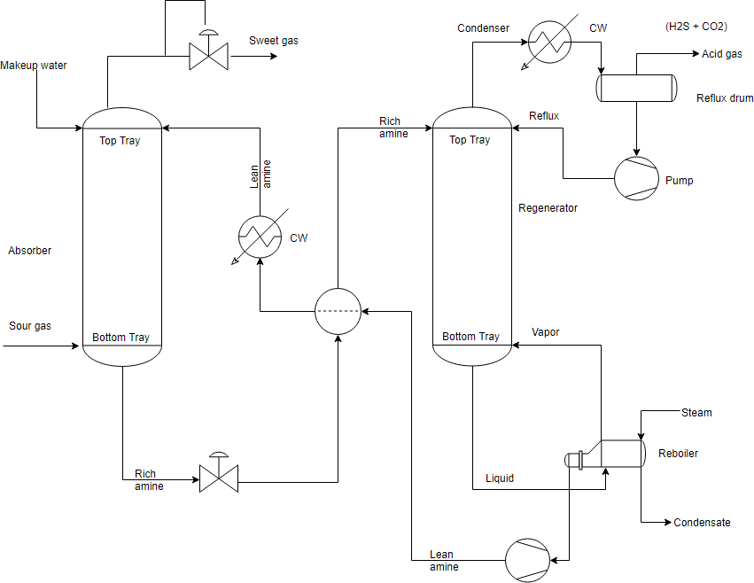
Process flow diagram examples – Amine Treating Plant*
The process flow diagram below depicts a single chemical engineering unit process known as an amine treating plant: (*Source: Wikipedia)
Process flow diagram examples – Air Dryer and Filter System
Instrument air is made available to the instrument air headers by compressing the atmospheric air. The compressed air being used for instruments is needed to be dry to a certain extent, whereas ambient air usually comes with moisture. When the moist air is compressed, some of the water content tends to condense under pressure and is removed using knock out drums at the discharge of instrument air compressors. The air coming out of knock out drums is still somewhat moist and further drying of this air is carried out by using Instrument Air Dryer and Filter System.
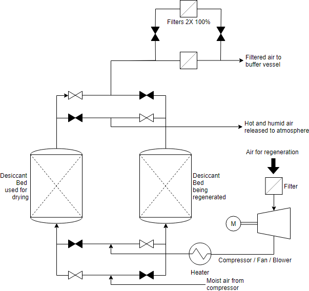
(*Source: enggcyclopedia.com)