The UML Class diagram is a graphical notation used to construct and visualize object oriented systems. A class diagram in the Unified Modeling Language (UML) is a type of static structure diagram that describes the structure of a system by showing the system's:
classes,
their attributes,
operations (or methods),
and the relationships among objects.
A class represent a concept which encapsulates state (attributes) and behavior (operations). Each attribute has a type. Each operation has a signature.
The class name is the only mandatory information depending on how details you want it to to.
The choice of perspective depends on what stage you are at in the development process. For example, in developing a domain model, you will rarely move beyond a conceptual perspective. Analytical models typically use a mix of conceptual and normative perspectives. The development of a design model will usually start with an emphasis on the normative perspective and then progress to the implementation perspective.
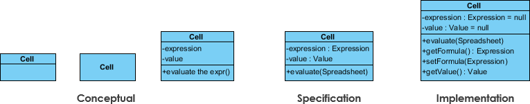
A diagram can be interpreted from different perspectives.
Conceptual: represents concepts in the domain
Specification: focuses on the interfaces to abstract data types (ADTs) in the software
Implementation: describes how classes will implement their interfaces, i.e. attributes and operations.


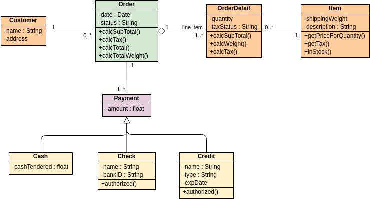
 Class Diagram Example")


")


