A use case, a concept invented by Ivar Jacobson at 1992, is a sequence of transactions performed by a system that yields an outwardly visible, measurable result of value for a particular actor. A use case typically represents a major piece of (end-to-end) functionality that is complete from beginning to end.
Use case diagrams are used during requirements elicitation and analysis as a graphical means of representing the functional requirements of the system. Use cases are developed during requirements elicitation and are further refined and corrected as they are reviewed (by stakeholders) during analysis. Use cases are also very helpful for writing acceptance test cases. The test planner can extract scenarios from the use cases for test cases.
Note: A use case describes how a type of user (or known as an actor) uses a system to achieve a particular user goal.
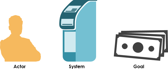
Thus, there are three key things we need to know to describe a use case:
- The actor or actors involved. An actor is a type of user (for example, cardholder) that interacts with the system.
- The system being used.
- The functional goal that the actor achieves using the system the reason for using the system.
Use Case at a Glance
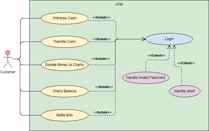
A use case diagram is a visual representation of the relationships between actors and use cases together that documents the system’s intended behavior. There is no rocket science to it at all: a usage case is simply a reason to use a system. For example, a bank cardholder might need to use an ATM to get cash out of their account. It is as simple as that.
Elements of Use Case Diagram
|
Notation Description |
Visual Representation |
Actor
|
|
Use Case
|
|
Communication Link
|
|
Boundary of system
|
 |
Structuring Use Case Diagram with Relationships
Use cases share different kinds of relationships. Defining the relationship between two use cases is the decision of the software analysts of the use case diagram. A relationship between two use cases is basically modeling the dependency between the two use cases. The reuse of an existing use case by using different types of relationships reduces the overall effort required in developing a system. Use case relationships are listed as the following:
|
Use Case Relationship |
Visual Representation |
Extends
|
 |
Include
|
 |
Generalization
|
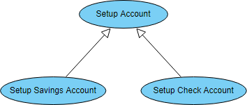 |
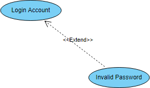
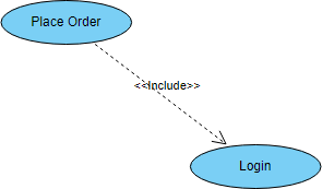
<<include>> vs <<extend>> use case
It is common to be confused as to whether to use the include relationship or the extend relationship. Consider the following distinctions between the two:
- Use Case X includes Use Case Y: X has a multi-step subtask Y. In the course of doing X or a subtask of X, Y will always be completed.
- Use Case X extends Use Case Y: Y performs a sub-task and X is a similar but more specialized way of accomplishing that subtask (e.g. closing the door is a sub-task of Y; X provides a means for closing a blocked door with a few extra steps). X only happens in an exceptional situation. Y can complete without X ever happening. In general, the extend relationship makes the use cases difficult to understand. It is suggested that developers use this relationship sparingly.
Use Case Levels of Details
Use case granularity refers to the way in which information is organized within use case specifications, and to some extent, the level of detail at which they are written. Achieving the right level of use case granularity eases communication between stakeholders and developers and improves project planning.
Alastair Cockburn in Writing Effective Use Cases gives us an easy way to visualize different levels of goal level by thinking in terms of the sea:

Note that:
- While a use case itself might drill into a lot of detail about every possibility, a use-case diagram is often used for a higher-level view of the system as blueprints.
- It is beneficial to write use cases at a coarser level of granularity with less detail when it’s not required.
Want a Free Use Case Diagram Tool?
The FREE drawing tool, Visual Paradigm Online (VP Online) Express Edition, supports UML, ERD and Organization Chart. You can draw a Use Case Diagram quickly through the intuitive UML drawing editor. The free UML tool has no ad, no limited period of access and no limitations such as number of diagrams, number of shapes and etc. Draw UML freely. And you own the diagrams you created for personal and non-commercial purposes.

Key features and benefits
- Unlimited period of access
- Unlimited number of diagrams
- Unlimited number of shapes
- UML tool, ERD tool, Org Chart maker, Floor Plan Designer, Business Concept Diagram, ITIL
- Optionally upgraded to paid editions for more diagram types and features
- Cross-platform: Windows, Mac, Linux. Compatible with all web browsers
- Easy to use: Create and connect shapes with drag and drop. Connectors are stuck to shapes and never separate apart.
- Apply different formatting options (shape and lines, solid and gradient paint), 40+ connector types, RTF caption, font options, shadow effect, etc
- Draw your own diagrams with your own shapes.
- Visio drawing and stencil import
- Easily embed text, external images and web links to diagram
- Print, export and share your work in different formats (PNG, JPG, SVG, GIF, PDF)
- Hundreds of diagram examples and diagram templates to help to start quickly
- Google Drive Integration