Specification and Description Language (SDL) is a modeling language used to describe real-time systems. SDL diagram illustrates the process of specification and description language modeling. It could be widely used in systems of automotive, aviation, communication, medical, and telecommunication fields.
There are three parts to an SDL diagram: the system definition, block and process. The system definition defines the major nodes (blocks) of the system such as clients and servers, while the block charts show more details. The process diagram shows the processing steps in each block. See state machine and UML.
Organization of SDL
System – The overall design is called the system and everything that is outside the system is called the environment. There is no specific graphical representation for the system but the block representation can be used if needed.
Agent – An agent is an element in the system structure. There are two kinds of agents: blocks and processes. A system is the outermost block.
| Element | Description | Symbol |
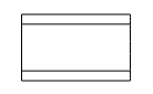
| Block | ·A block is a structuring element that does not imply any physical implementation on the target.
·A block can be further decomposed in blocks and so on allowing to handle large systems. ·A block symbol is a solid rectangle with its name in it |
 |
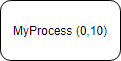
| Process | A process is basically the code that will be executed. It is a finite state machine based task and has an implicit message queue to receive messages. It is possible to have several instances of the same process running independently. The number of instances present when the system starts and the maximum number of instances are declared between parentheses after the name of the process.
The full syntax in the process symbol is: <process name>[(<number of instances at startup>, <maximum number of instances>)] If omitted default values are 1 for the number of instances at startup and infinite for the maximum number of instances. |
|
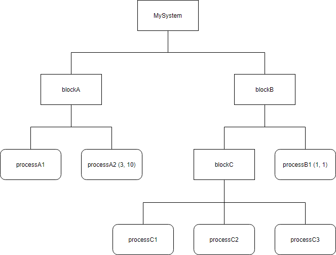
Architecture – the overall architecture can be seen as a tree where the leaves are the processes.
Edit this Diagram
Behavior
First of all a process has an implicit message queue to receive the messages listed in the channels. A process description is based on an extended finite state machine. A process state determines which behavior the process will have when receiving a specific stimulation. A transition is the code between two states. The process can be hanging on its message queue or a semaphore or running e.g. executing code. A message stimulus coming from the environment or from another agent to an agent is called a signal. Signals received by a process agent are first placed in a queue (the input port). When the state machine is waiting in a state, if the first signal in the input port is enabled for that state it starts a transition leading to another state.
| Elements | Description | Symbol |
| Start | The start symbol represent the starting point for the execution of the process |  |
| State | The name of the process state is written in the state symbol |  |
| Stop | A process can terminate itself with the stop symbol. |  |
| Message input | The message input symbol represent the type of message that is expected in an SDL-RT state. It always follows an SDL-RT state symbol and if received the symbols following the input are executed.
The syntax in the message input symbol is the following: <Message name> [(<parameter name> {, <parameter name>}*)] <parameter name> is a variable that needs to be declared. |
 |
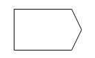
| Message output | A message output is used to exchange information. It puts data in the receiver’s message queue in an asynchronous way.
<message name>[(<parameter value> {,<parameter value>}*)] TO_XXX… |
 |
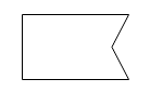
| Message save | A process may have intermediate states that can not deal with new request until the on-going job is done. These new requests should not be lost but kept until the process reaches a stable state. Save concept has been made for that matter, it basically holds the message until it can be treated.
The symbol syntax is: <message name> |
 |
| Continuous signal | A continuous signal is an expression that is evaluated right after a process reaches a new state. It is evaluated before any message input or saved messages. |  |
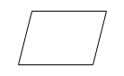
| Action | An action symbol contains a set of instructions in C code. The syntax is the one of C language. |  |
| Decision | A decision symbol can be seen as a C switch / case. |  |
| Semaphore take | The Semaphore take symbol is used when the process attempts to take a semaphore. |  |
| Semaphore give | To give a semaphore, the syntax in the ‘semaphore give SDL-RT graphical symbol’ is: <semaphore name> | 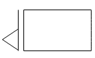 |
| Timer start | o start a timer the syntax in the ‘start timer SDL-RT graphical symbol’ is : <timer name>(<time value in tick counts>) | 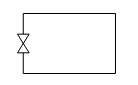 |
| Timer stop | To cancel a timer the syntax in the ‘cancel timer SDL-RT graphical symbol’ is : <timer name> | 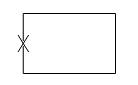 |
| Task creation | To create a process the syntax in the create process symbol is:
<process name>[:<process class>] [PRIO <priority>] |
 |
| Procedure call | The procedure call symbol is used to call an SDL-RT procedure.
The syntax in the procedure call SDL graphical symbol is the standard C syntax: [<return variable> =] <procedure name>({<parameters>}*); |
 |
| Connectors | Connectors are used to:
· split a transition into several pieces so that the diagram stays legible and printable, to gather different branches to a same point. |
 |
| Transition option | The branches of the symbol have values true or false. The true branch is defined when the expression is defined so the equivalent C code is: #ifdef <expression> |  |
| Comment | The comment symbol allows to write any type of informal text and connect it to the desired symbol. If needed the comment symbol can be left unconnected. |  |
| Extension | The extension symbol is used to complete an expression in a symbol. The expression in the extension symbol is considered part of the expression in the connected symbol. Therefore the syntax is the one of the connected symbol. |  |
| Procedure start | This symbol is specific to a procedure diagram. It indicates the procedure entry point. |  |
| Procedure return | This symbol is specific to a procedure diagram. It indicates the end of the procedure. |  |
| Text symbol | This symbol is used to declare C types variables. |  |
| Additional heading symbol | This symbol is used to declare SDL-RT specific headings |  |
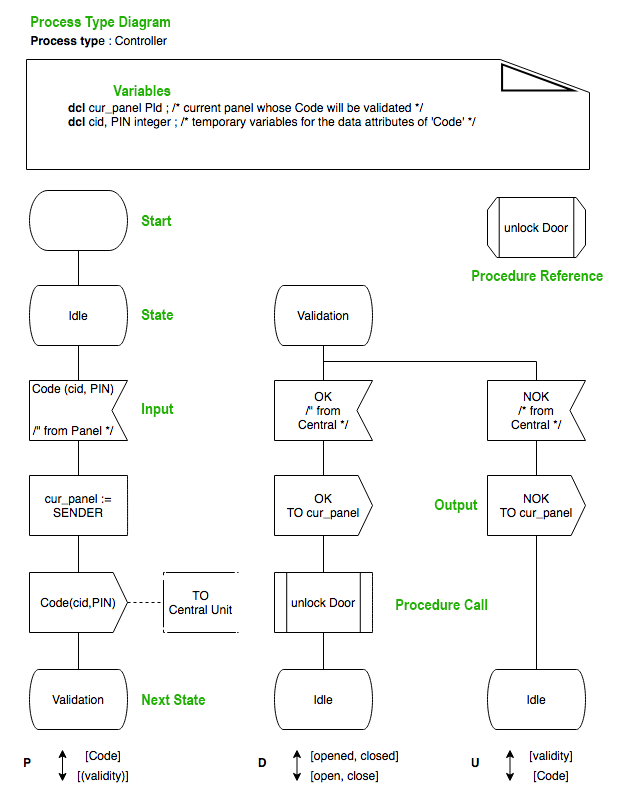
Example on Behavior
In a state (e.g. Idle) the process takes from the queue the first signal that is of one of the types indicated in the input symbols (here Code, containing information about the card id and PIN from the Panel). The Idle state is followed by one input symbol which describes the consumption of the signal Code. In the transition following the reception of the Code signal, it will use the variable cur_panel to remember from which panel the signal came from and then send the Code to the central unit for validation. The next state is Validation. In state Validation the Controller will only accept OK or NOK. If it gets OK it will open the door by calling the procedure OpenDoor.
Edit this Diagram
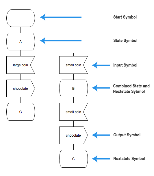
SDL vs State Machine Diagram
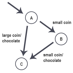
A chocolate vending machine is an automated machine that provides different types of chocolate after appropriate code inserted.
State Machine
A finite state machine consists of a finite number of states, one being the initial state and a number of transitions connecting the states.
In the vending machine (state diagram example) below the circles represent states, and the arrows represent transitions. Each arrow is decorated witch an input which triggers the transition ( before slash ) and a possible list of outputs ( after slash ).